Setup
Below, we describe how to setup FOBOS 2.0 hardware and software and test that everything is working. This page only describes setting up the control board and software for acquisition and anlysis. For DUT board please refer to DUT Board Setup.
Requirements
- Digilent Basys3 board (control board).
- A PC with Linux installed.
- Python2.7 installed.
- Xilinx Vivado 2017.2.
- Picoscope 5000 series.
Software Setup
Note: The following installation procedure is tested on Linux Ubuntu 16.04 and 18.04.
- Download FOBOS from the FOBOS home page.
- Extract the archive into the directory of your choice
$ tar xvfz fobos-v2.0.tgz
- Use the following commands to install pip and few necessary Python packages:
$ sudo apt-get install python-pip
$ tar xvfz fobos-v2.0.tgz  again?
$ cd fobos
$ sudo pip install -r requirements.txt
Control board Setup
Follow these steps to compile the control software, generate the bitstream and program the control board.
- Build the control board Vivado project.
$ cd capture/ctrl/basys3ctrl/vivado
$ make project
- A Vivado project will be created at fobos/capture/ctrl/basys3ctrl/vivado/basys3ctrl. Open it using Vivado.
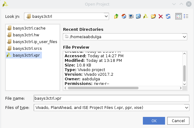
Open Vivado project
- In Vivado’s Flow Navigator window, click ‘Generate Bitstream’.
- After bitstream is generated, export the hardware. Click File > Export > Export Hardware … make sure to select ‘Include bitstream’.
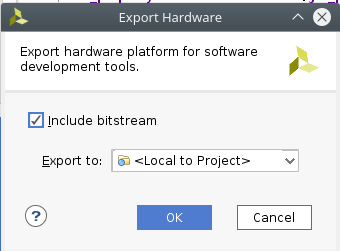
Export Hardware
- Launch the Xilinx SDK (File > Launch SDK).
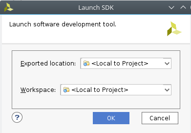
Launch SDK
- In the SDK, create a new empty project(File> New application project). Set the project name to ctrl and select the hardware platform, click Next and make sure you select ‘Empty Application’.
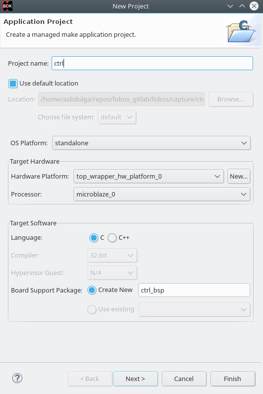
Create Project
If this fails, make sure that zlib1g-dev and zlib1g:i386 are installed on your machine.
$sudo apt-get install zlib1g-dev zlib1g:i386
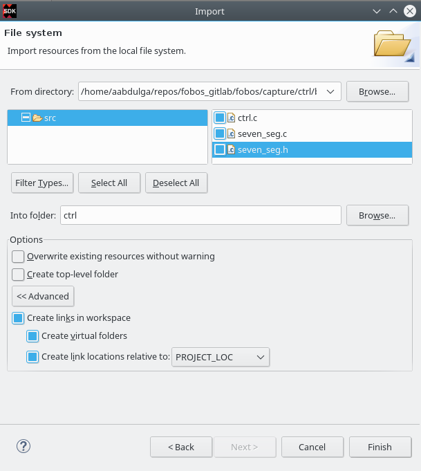
- Link all the .c and .h files in the fobos/capture/ctrl/basys3ctrl/sdk/src/ to the project (right-click on ctrl/src folder -> Import -> General-> file system -> browse to folder). make sure to check “Advanced-> Create links in the workspace” and “Create virtual folders” .
Launch SDK
- Program the control borad FPGA. Connect the Basys3 board to your PC via USB. In the Xilinx Tools menu, select Program FPGA. Make sure the correct device is selected and then click on Program.
- Run the control software. Make sure to select the ctrl project created in step 6 then go to the Run menu and select ‘Run’.
- You should see the word CERG in the seven-segment display of the Basys3 board.
Testing the control board
To make sure the control board is working, you can run the dymmyCaptureBasic.py script in the fobos/software directory. This script send data to the board wich echos data back.
$ cd path-to-fobos/software
$ python dummyCaptureBasic.py
Sending configuration...
f0030006000900000001
Status= 00000000
f0030006000000000007
Status= 00000000
Sending data..
f001001e00c0000761996dc996d4ac00c100070f7821507a22a00081000700800001
OK.    Status= 00000000
61 99 6d c9 96 d4 ac
f001001e00c00007fd8771fe717de400c100073e1fe5b4aa357c0081000700800001
OK.    Status= 00000000
fd 87 71 fe 71 7d e4
f001001e00c0000782051f5484702200c10007980d05d4ea25bc0081000700800001
OK.    Status= 00000000
82 05 1f 54 84 70 22
f001001e00c0000767881b702afe5200c10007b08a5e036de72b0081000700800001
OK.    Status= 00000000
67 88 1b 70 2a fe 52
f001001e00c0000726a1d601ccdf7a00c1000773539e52672d5d0081000700800001
OK.    Status= 00000000
26 a1 d6 01 cc df 7a
If you see this output, your control board is now ready!