4.3.1. AES Example
As part of FOBOS, we provide a simple AES-128 implementation in VHDL. The VHDL code for this AES implementation is
provided in the directory dut/example_cores/AES-128. The block diagram of this implementation is shown in
Fig. 4.8 and the technical details in Table 4.3.
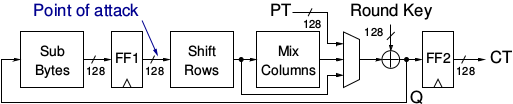
Fig. 4.8 Block Diagram of the Example AES Implementation
Interface |
AXI |
PDI width |
128 |
SDI width |
128 |
DO width |
128 |
Rounds per clock cycle |
1 |
Clock cycles for encrypting one block |
11 |
4.3.1.1. First Steps
Create a new directory for the AES DUT project for example AES-DUT.
Copy all files of the example AES from the dut/example_cores/AES-128/vhdl directory, all files from the
dut/fpga_wrapper/src_rtl directory and the dut/fpga_wrapper/src_tb/core_wrapper_tb.vhd to this directory.
Additionally copy the constraint file that matches your DUT from the dut/fpga_wrapper/constraints directory.
Only modify the copied files. The example below assumes that you have installed FOBOS in /opt
and that your DUT is the FOBOS FBD-A7.
mkdir AES-DUT
cd !$
cp /opt/fobos/dut/example_cores/AES-128/vhdl/* .
cp /opt/fobos/dut/fpga_wrapper/src_rtl/* .
cp /opt/fobos/dut/fpga_wrapper/src_tb/core_wrapper_tb.vhd .
cp /opt/fobos/dut/fpga_wrapper/constraints/FOBOS_Artix7.xdc .
4.3.1.2. AES Top Level Interface
The top level file of the example AES implementation is aes_axi.vhd. Its interface is shown in Listing 4.2.
It features three AXI4-Stream compatible interfaces, one for plaintext (PDI), key (SDI), and ciphertext (DO) as
well as a clock and reset input. This interface matches exactly the FOBOS wrapper’s interface for the Crypto Core.
It is a wrapper for the basic AES implementation.
entity aes_axi is
    Port ( clk       : in  STD_LOGIC;
           rst       : in  STD_LOGIC;
           pdi_data  : in  STD_LOGIC_VECTOR (127 downto 0);
           pdi_valid : in  STD_LOGIC;
           pdi_ready : out STD_LOGIC;
           sdi_data  : in  STD_LOGIC_VECTOR (127 downto 0);
           sdi_valid : in  STD_LOGIC;
           sdi_ready : out STD_LOGIC;
           do_data   : out STD_LOGIC_VECTOR (127 downto 0);
           do_valid  : out STD_LOGIC;
           do_ready  : in  STD_LOGIC
                      );
end aes_axi;
The file aes_axi translates the very simple interface of the basic AES implementation which uses out-of-band
signaling. It is shown in Listing 4.3. It expects
one block of plaintext or 128-bit, and one 128-bit key on the input and produces 128-bit ciphertext. It has a clock
signal and is idle until start is applied. Once the output is ready, it asserts the done signal. As start and
done are explicit signals and not part of the data_in, key_in, or data_out signals, we call then out-of-band.
On the other hand, in-band signaling, as used by the LWC Hardware API (see Section 4.2.4) requires
a comprehensive protocol of commands and parameters being sent and received via PDI, SDI, and DO.
entity aes_non_pipe is
port (
    clock    : in  std_logic ;
    start    : in  std_logic ;
    data_in  : in  std_logic_vector (0 to 127);
    key_in   : in  std_logic_vector (0 to 127);
    data_out : out std_logic_vector (0 to 127);
    done     : out std_logic
);

end aes_non_pipe;
It is therefore easily possible to adjust the file aes_axi to other block cipher implementations which use
such simple out-of-band signaling.
Note
FOBOS is not concerned with what data is transmitted to PDI, SDI, or comes from DO, i.e., whether the Crypto Core requires in-band signaling (LWC Hardware API) or not. FOBOS only needs to know which data goes to which FIFO and how deep the FIFO has to be. FOBOS does not support out-of-band signaling. If that is required it has to be derived from the AXI protocol as in the example AES, or the FOBOS protocol has to be adjusted.
4.3.1.3. FOBOS Wrapper Configuration
The AES example has an AXI interface and has to be instantiated as follows in the core_wrapper.vhd file around line 173.
These are the default settings for this file. Note that the reset signal has to be inverted.
--=============================================
-- BEGING USER CRYPTO
-- Instantiate your core here
crypto_core : entity work.aes_axi(behav)
port map(
    clk         => clk,
    rst         => not crypto_input_en,
    -- data signals
    pdi_data    => crypto_di0_data,
    pdi_valid   => crypto_di0_valid,
    pdi_ready   => crypto_di0_ready,

    sdi_data    => crypto_di1_data,
    sdi_valid   => crypto_di1_valid,
    sdi_ready   => crypto_di1_ready,

    do_data     => crypto_do_data,
    do_ready    => crypto_do_ready,
    do_valid    => crypto_do_valid

    --! if rdi_interface for side-channel protected versions is required, uncomment the rdi interface
    -- ,rdi_data => crypto_rdi_data,
    -- rdi_ready => crypto_rdi_ready,
    -- rdi_valid => crypto_rdi_valid
);
-- END USER CRYPTO
--=============================================
The example AES expects one block of plaintext or 128-bit, and one 128-bit key on the input. These have to
be placed on FIFO_0 and FIFO_1 respectively. As the width of PDI and SDI are 128-bit, the width of
these FIFOs have to match and they have to be only one word deep.
The output of this AES is also 128-bit wide, hence FIFO_OUT also has to be 128-bit wide and one word deep.
This has to be defined in core_wrapper_pkg.vhd which is shown in Listing 4.5.
This is also the default configuration of this file.
package core_wrapper_pkg is
    -- input fifos
    constant FIFO_0_WIDTH           : natural := 128    ;
    constant FIFO_0_LOG2DEPTH       : natural := 1      ;
    constant FIFO_1_WIDTH           : natural := 128    ;
    constant FIFO_1_LOG2DEPTH       : natural := 1      ;
    -- output fifo
    constant FIFO_OUT_WIDTH         : natural := 128    ;
    constant FIFO_OUT_LOG2DEPTH     : natural := 1      ;
    -- random data
    constant RAND_WORDS             : natural := 8      ;
    constant FIFO_RDI_WIDTH         : natural := 64     ;
    constant FIFO_RDI_LOG2DEPTH     : natural := 3      ;

end core_wrapper_pkg;
Note
The depth of a FIFO is \(2^{FIFO\_x\_LOG2DEPTH}\). For example if FIFO_x_LOG2DEPTH = 2, the depth of the FIFO is \(2^2 = 4\). FIFO_x_LOG2DEPTH has to be equal or larger than 1, i.e. the minimum depth of the FIFO is 2.
4.3.1.4. Generating Bitstream for DUT
Create a project in Vivado e.g., AES-FBD-A7 and add all source files that you copied in your project
directory e.g., AES-DUT and the constraint file.
Select the FPGA device that is on your DUT. You can find that information in the DUT descriptions in Section 4.1.
Make sure that the file core_wrapper_tb.vhd is only used for Simulation. This can be set in the
Source File Properties window.
Select the file half_duplex_dut.vhd as the top level. Don’t run synthesis yet!
Some files use the 2008 standard of VHDL. Vivado 2022.1 does not detect this and will create error messages when synthesizing the code. Note: You don’t need to use Vivado 2022.1 to implement the DUT, you can use newer versions but they might still create the same error.
As it is too tedious to set the VHDL revision of all files that use the 2008 standard individually, you can type the following command into the TCL Console of Vivado to apply this to all files.
set_property FILE_TYPE {VHDL 2008} [get_files *.vhd]
Now you can run Synthesis followed by Implementation and Generate Bitstream.
The resulting bit file will be in the directory ~/AES-DUT/AES-FBD-A7/AES-FBD-A7.runs/impl_1 by
the name of half_duplex_dut.bit. Copy this file into your Jupyter Notebook directory, maybe under
a more descriptive name.
cp ~/AES-DUT/AES-FBD-A7/AES-FBD-A7.runs/impl_1 ~/notebooks/fobos/aes_fbd-a7.bit